Projects
Project 1 – Constitutive Modelling
“Mechanical Characterization of Curing Thermosets”
This project, “Mechanical Characterization of Curing Thermosets”, dealt with the development of a constitutive model describing the evolving viscoelastic properties of curing thermosets (epoxies). The final goal of the work is to obtain insight in the development of residual stresses due to curing induced shrinkage of the epoxy. Epoxies are applied in e.g. electronics or composite structures.
The difficulty lies in the fact that two time scales interfere; the viscoelastic process and the curing process have different time scales which have continuous interaction. An experimental procedure was developed, measuring the thermo-viscoelastic properties at more or less constant degrees of cure, via Dynamic Mechanical Analyses while quenching the curing via a rapid cooling down. Special tools were developed to capture the transition of liquid resin to a solid polymer.
The final model captures the curing-induced development of the viscoelastic moduli quite well. In follow-up projects the approach is used to estimate residual stress states in electronic components.
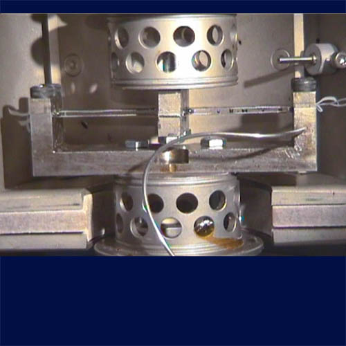
Photo of the ‘sandwich beam tool’, used to measure the evolving viscoelastic properties of epoxy resin from liquid to solid states in the Dynamic Mechanical Analyser (DMA). The resin in between two leaf springs turns these parallel springs into a sandwich beam. The DMA measures the stiffness of the beam. 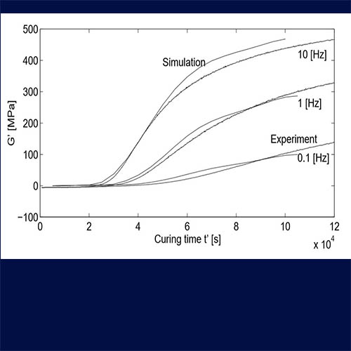
Development of the viscoelastic storage modulus (shear stiffness) with curing time, model versus experiment.
Project 2 – Structural response modelling
“Modelling the dynamic behaviour of the anvil”1
Objective: Development of a swift, structural response model for the dynamic behaviour of the anvil to be used in pile driveability analyses
It is common practice to perform wave equation driveability analyses in order to assess the adequacy and performance of the driving hammer selected for the installation of foundation piles as well as the driving stress induced fatigue damage. In commercial software the anvil, transferring the hammer load from the ram towards the pile wall, is assumed rigid. However, the larger the pile, the larger the anvil and the less it will behave like a rigid body. This paper describes the findings of modelling the dynamic behavior of the anvil during pile driving, in order to come to more realistic pile driving predictions, especially in large diameter piles. A semi-analytical model capturing the dynamic deflection of the anvil was developed, based on the Lagrange equation. This flexible anvil model was validated against finite element results as well as against field data. The response of the combined model for ram, flexible anvil and pile reflects both finite element and field data very well, at least if contact between the three bodies is established via a penalty stiffness approach. An impulse-based contact mechanics approach did not bring the expected numerical robustness. The use of the flexible anvil model significant increases both calculated energy transfer to the pile and calculated peak force, thus likely affects pile driveability predictions and estimation of fatigue damage, too. Taking into consideration a) the cost impact of a realistic hammer selection, and b) the possible benefits of a more precise evaluation of the fatigue damage as a result from stress estimation during driving, it is recommended to consider this flexible anvil behavior for more accurate drivability predictions, especially for large diameter piles. Future validation of the suggested anvil modelling with more field data is considered as necessary to further improve its accuracy.
1 Work done while being employed at IHC IQIP.
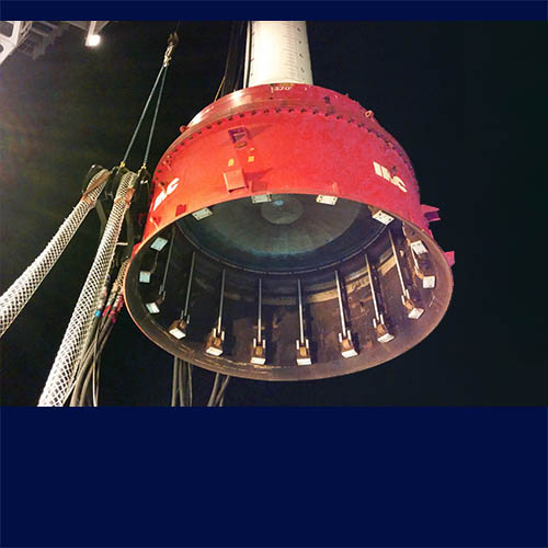
Piling hammer – sleeve assembly. The anvil is the large disk seen here as ‘ceiling’ of the sleeve. 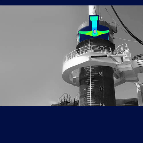
Piling hammer – sleeve assembly on top of monopile
Project 3 – Structural response modelling
“Blast-loaded bulkhead modelling”2
Objective: Development of a swift, structural response model for blast-loaded bulkheads to be used in TNO’s ship vulnerability code.
An analytical model is developed for analysis of the dynamic elastic-plastic response of structural stiffened panels (e.g. bulkheads) due to blast. The model accounts for pinned boundaries and panel aspect ratios in the range of 1 – 5. Both the short span and long span deflection shapes are accounted for, as well as stiffeners in both directions. The Lagrange equation has been applied to translate the energy balance into a set of equations of motion, being solved numerically. In order to account for the stiffness and deformation of the surrounding structure (e.g. a ship), flexible boundaries are introduced allowing in-plane edge displacements. Specific edge response due to a blast loaded bulkhead has been fitted by a SDOF dynamic model based on series of FEM simulations of a real ship structure. The analytical model results have been compared to FEM simulations for some stiffened panels responses showing good agreement with the analytical model.3
Approach:
- Choose modelling strategy based on literature review
- Develop model according to chosen strategy;
- Set-up analytical equations for elasto-plastic deformation energy, kinetic energy and work, per unit volume. Supported by Maple
- Set-up numerical volume integration scheme for energies and work
- Derive equations of motion via Lagrange equation
- Calibrate and validate model in Matlab via Finite Element Modelling (LS-Dyna)
- Handed over to developers of vulnerability code
2 While being employed at ![]()
3 Abstract from C. van ‘t Hof, A.G. van Erkel and G. Pape, “Analytical modelling of bulkhead blast response”, Proceedings of 25th Military Aspects of Blast and Shock (MABS25), September 2018
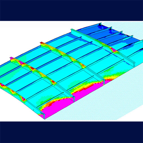
Finite element model of quarter deck panel, used as validation. Picture shows plastic strain under blast load. 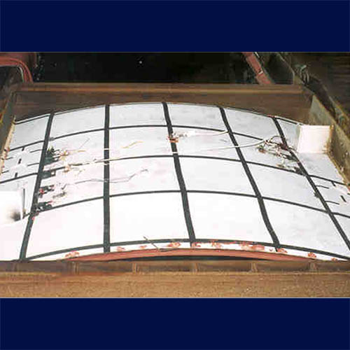
Blast-tested bulkhead section.